My first computer.
In 1965-1966, computer access was
hard to come by. So I built my own.
|
|
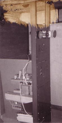
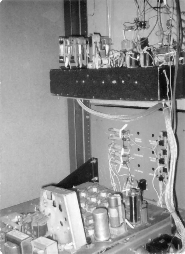
Front view
Tape reader, version 2, at
top.
Control unit.
Memory (8 words of 7 bits each)
Arithmetic unit
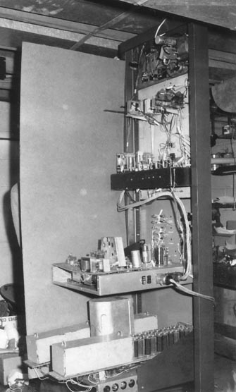
Rear view
Early power supply (inadequate)
at top.
Tape reader
Control unit
Memory, with cover on Strowger
switch.
Arithmetic unit.
|
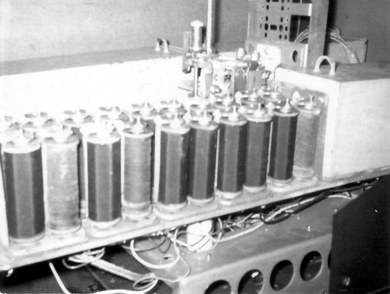 |
Memory
8 words of 7 bits.
Those are long-coil telephone
relays. One of four banks are uncovered. Behind the relays is a Strowger
two-dimensional stepping switch, the memory accessing device.
|
 |
Arithmetic
unit
Add, subtract, and shift.
Data transfer to and from other
units is bit-serial, through a stepping switch hidden by the support brackets.
|
 |
Paper tape
reader and
control unit
At top, the control logic for
the paper tape reader.
At bottom, the control unit.
The large trapezoidial object
on the control unit is an up-down counter removed from a junked jukebox
coin mechanism. It was used as the relative branch controller, indicating
how many instructions on the paper tape were to be skipped.
The filter capactitor and tall
relay were the system clock for data transfers between units. About 1.5
Hz.
|
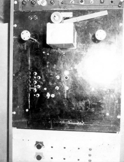 |
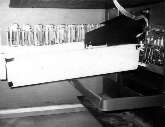
Tape reader
early version.
Roller skate wheels above contacts.
Wasn't reliable.
The tape was 4 data bits and
a clock track. Tape input could be simulated manually using the buttons
at the left. Data read from tape appeared in the lamps at left.
At the bottom is the front
of the control unit, with big Start. Stop, and Reset buttons.
|
| Not shown: output typewriter
(an old manual typewriter, equipped with solenoids for zero, one, space,
and CR only) and power supply. |
|
The machine had, as I recall, 14
instructions. These were expressed as four bits on the tape, plus a clock track,
which appeared between the rows of data bits. The tape was the program, and
was cranked back and forth by two Erector set motors with solenoids on the gearshifts.
The tape would be threaded and attached
firmly to the reels, and the RESET and START buttons pushed. This started the
tape forward. The four data tracks would be read and latched into a 4-bit instruction
register built out of telephone wire relays. When the clock track was read,
the control unit executed the instruction specified by the four bits and cleared
the instruction register.
For simple instructions, the tape
did not stop. But for long instructions, the control unit stopped the tape drive
by shifting the takeup reel motor into neutral, and started the 1.5Hz data transfer
clock. Long instructions included add, subtract, store, and print. Bits were
transferred serially between the arithmetic unit and the memory or printer,
at 1.5Hz.
Branching was provided. Branching
was conditional or unconditional, and forwards or backwards. Branching was performed
by specifying the number of "mark" instructions to be skipped in the
forward or backwards direction. The "branch" instruction itself caused
the control unit to ignore all instructions other than "mark", while
winding the tape forwards or backwards as required, counting down the number
of marks to be ignored. When the number of marks to ignore reached zero, normal
operation was resumed. The large trapezoidial object in the control unit, an
up-down counter salvaged from a jukebox, controlled branching. Conditional branching
was limited to "branch if accumulator negative", which is sufficient.
The big limitation was the paper
tape reader, built to use adding machine tape punched with a hand punch. Three
versions were built. The first was photoelectric, using cadmium sulfide photocells
and "Little Jewel" high-sensitivity R/C radio relays. The problem
was that the pull-in and release currents for the relays were too far apart,
and while they'd detect a hole, they wouldn't drop out after the hole passed.
Three decades later, it occurs to me that all I needed to do was make the tape
black using black ink and a roller.
The second tape reader was mechanical,
and is shown above. Reliable contact couldn't be achieved with metal strips
against roller skate wheels. Finally, with time running out for the science
fair, a brute-force solution was tried - vinyl seat cover material in place
of paper tape, and staples to store the information. This worked, but limited
program size severely, because the tape was so thick and filled the reels quickly.
Most of the parts came from surplus
stores in the Washington, D.C. area. A few parts, including the big Strowger
stepping switch, came from national surplus houses, such as Fair
Radio Sales or Herbach and Rademan,
both of which are still in business.
In retrospect, this was far too much
work for what it did.
J. Nagle
Revised September 1, 2002