One-legged hopping is the basis of running locomotion. This result comes from Raibert, [5][6] who revolutionized locomotion research by focusing on balance rather than gait. Once controlled hopping has been achieved, running is an emergent behavior obtained by minor re-tuning of the hopping controller.
The state of the art in legged locomotion control is that running on the flat is well-understood, but the fast navigation of rough terrain remains an unsolved problem. The approach taken is to look in detail at some subtle issues in legged running that have not been previously addressed.
This is an attempt to understand one of the basic things animals do: move around competently in rough terrain, one of the first jobs brains evolved to handle. Understanding that job may give insight into the levels of "intelligence" that evolved early, and yield building blocks for strong AI. Meanwhile, animation with physically correct movement tends to look realistic, which provides a commercial application for the technology.
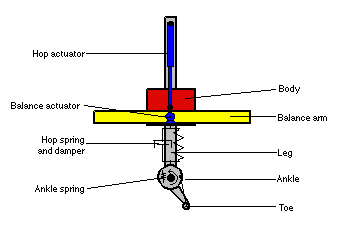
The starting point for this work is the planar hopper as described by Raibert and by Lapshin [3][4]. This minimal legged locomotion system is a one-legged hopping machine constrained to operate in a plane. It has two actuators, a balance actuator which applies a torque between the "leg" and "body", and a hopping actuator which extends the "leg". The hopper is unstable; without control it will fall.
For animation purposes, we need a simulated environment. Unlike most simulated environments, the one we use (Working Model, a commercial dynamics simulator from Knowledge Revolution, Inc. ) has realistic physics. Joints, gravity, inertia, general collisions, and friction (static, sliding, and air) are all simulated. The terrain can vary in slope, in friction, and in elasticity. Obstacles, both moving and stationary, may be present. The hopper can bump into things, slip, fall, and try to recover. The result is in some ways closer to a real-world environment than the benign indoor environment in which most research robots operate. We can also afford crashes and falls, which is useful if we intend to do "learning" The main drawback of the simulated environment is that it is a 2D system. A 3D system is being developed.
Despite the simplicity of both the hopper and its simulated environment, the introduction of irregular terrain and friction forces us to look beyond the usual solutions toward more "animal-like" control approaches. This brings us much closer to dealing with the issues that dominate locomotion in the real world of rough and varying terrain.
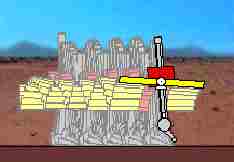
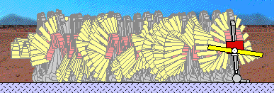
The basic control strategies are simple: during stance (the foot-solidly-on-ground phase), level the balance arm; during flight, align the leg with the motion vector anticipated at landing. Travel direction and speed are controlled by biasing the leg angle during flight. Figure 2 illustrates these strategies in action. The hopper is moving from left to right, and the outline of the hopper has been drawn every 50ms. Note how the balance arm moves; the alignment of the leg during flight requires that the balance arm, as a reaction mass, be displaced from level, and the re-levelling of the balance arm during stance forces the body and leg to lean forward, placing them in position for the next stride. There are subtle interactions here, and we will briefly examine them phase by phase.
We can identify at least the following issues in the control of the flight phase:
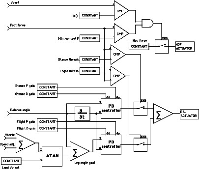
Raibert uses two proportional-derivative (PD) controllers, one for the stance phase and one for the flight phase, and a five-state state machine to sequence the hopping cycle. In our work, the state machine has been eliminated. Instead, the appropriate PD controller is enabled based on the input variables and their derivatives. This stateless controller provides a modest increase in robustness; there's no possibility of getting the state machine out of sync with the hopper.
The control loop is computed at 50ms intervals. A full hop requires about 1s. This is a rather slow controller by modern standards. The control loops are run with large errors at the beginning of each phase, with the gains adjusted to bring the error to zero only near the end of the phase, resulting in "soft" control loops that work with the dynamics of the mechanical system, rather than fighting them.
The controller we use has ten tuning parameters, which appear as "constant" blocks on the control diagram. Most of these parameters can usefully be changed to exert control over the hopping system.
The tuning parameters are reasonably orthogonal; one can change a single parameter and affect the locomotion cycle in a predictable way. This tuning parameter space is more benign than joint space, and a good working space for higher-level control techniques. We expect to do some automatic tuning of these parameters in future work, but in the current system they are all tuned manually. In this paper, we are concentrating on control issues below the locomotion controller just described. To demonstrate the need for additional lower-level controllers, we will try to climb a hill, and see what happens.
The geometry of foot-ground contact is shown in Figure 7.
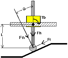
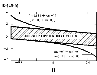
The foot/ground contact being simulated is a rubber foot on clay ground, with a static friction coefficient K of 0.9. Slipping will occur unless the control system keeps the tangent component of the foot contact force vector Ft below KFn , where Fn is the normal component of the foot contact force vector. The length of the "leg", L, is a sensor input. The torque applied by the balance drive servo, Tb , and the force applied by the hop actuator, Fh , are actuator outputs. For simplicity, we are assuming a massless foot and leg here (in the simulation, these have masses, which tends to cause our estimates of Fh to be on the low (safe) side), and thus the effect of gravity is subsumed into Fh and Tb . The leg tilt with respect to the ground normal is [[theta]], and can be obtained from a "compliant foot" as mentioned above. From this available information, we can calculate Ft and Fn :
which leads to the constraint
There is a corresponding constraint for slopes in the other direction:
If we graph these constraints for the region of interest of [[theta]],
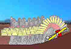
and with these torque limits, hill-climbing is successful. See Figure 5.
The only change between the unsuccessful hill-climb above and this one is the addition of the new anti-slip constraint control law. The shortened stride length on the hill is a consequence of the anti-slip constraint. The result is much more "realistic looking" than the typical "gait cycle" approach used in animation.
This anti-slip constraint is low-level. In the control hierarchy, the anti-slip system is below even the basic locomotion controller, and limits its authority. It's like an automotive anti-skid braking system both in function and in authority. Like an anti-skid braking system, within its area of authority the anti-slip controller is supreme. This is thus a true subsumption architecture; the low-level controller has the ultimate power. [1]
Hill-climbing is thus an emergent behavior which arises from slip control.
The anti-slip controller is also low-level from an input/output point of view. The inputs and outputs are all local to the leg system. A multi-legged creature would have an independent anti-slip controller for each leg. No input from attitude or balance sensors is required. We do need a friction estimator, but with suitable side-load sensing in the foot, even that could be handled at a low level. A planar hopping machine thus needs a 2-axis force sensing "ankle", akin to the force-sensing wrist devices used on manipulators, and a 3-D hopper needs a 3-axis "ankle".
An alternate approach is an adaptive friction estimator, which slowly increases the estimated friction coefficient until slip occurs, then backs it off by a factor larger than the usual ratios between static and sliding friction. That's the approach used in anti-skid braking systems, and requires a simple, fast, control loop. An active "ankle" joint, with a faster servo than the leg servos, would be an effective way to implement this in a real machine. The entire anti-slip control system could then be implemented within the ankle subsystem, with the larger and slower upstream joint servos controlled by the ankle deflection from neutral.
We deliberately created a situation at the edge of stability: the hopper was forced to run too fast on a slippery surface. This surface has a static friction of 0.20 and a sliding friction of 0.10, and the servo system has been given a conservative estimate of 0.08 for K. Slip was avoided, but the balance servo was torque-limited on almost every hop. Thus, the balance servo was unable to fully level the balance arm by the end of most stance phases. The balance arm even touched the ground twice. The stride length appears to have become chaotic. But the hopper didn't fall down. This control system is thus robust under even unreasonable conditions. This one is fun to watch as an animation; again, realistic looking motion emerges from the control system.
To be honest, if the friction estimate is set to 0.10, the hopper does slip and fall. It takes a few strides to do so, though, offering an opportunity to slow down and avoid disaster.

We tried three foot designs. Foot A, a simple block with a rotational spring at the joint, produced reaction forces before the foot had fully aligned with the ground, causing the stance servo to be activated prematurely with an incorrect ground angle estimate, resulting in slip. The next design, B, with a round, load-bearing heel and a passive, sprung ground angle probe, was an improvement, but was subject to error at the top of hills, when the angle sensor reached over the crest of the hill and underestimated the ascending slope. Addressing that problem yielded foot C.
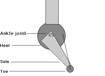
This foot has a rotational spring to push the toe down, a rubbery heel that supports the load, a slippery toe (K=0.2) to avoid tripping at the beginning of a hill, a "sole" to sense tops of hills, and a "rope" constraint to keep the foot from overextending and tripping on landing. Each feature was introduced to solve problems observed in simulation. The result is a surprisingly anthropometric foot.
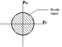
For the 3D one-legged hopper, slipping will occur unless the control system keeps the tangent component of the foot contact force vector Ft below KFn , where Fn is the normal component of the foot contact force vector. This is written
|Ft | < KFn
This is the same anti-slip constraint as for the planar hopper, except that Ft is now a 2D vector. If we resolve Ft into two perpendicular components Ftx and Fty, the constraint becomes
|Ftx + Fty | < KFn
This can be visualized as a circle with radius KFn in 2D transverse force space, with the area inside the circle being the region for which slip will not occur.
We could treat each axis as separate for anti-slip control purposes. This is not a complete solution, because friction does not apply separately for each axis. A conservative solution is to share the available friction equally between the axes. This can be implemented by multiplying the coefficient of friction by sin([[pi]]/4), which is 0.707, and use that lower frictional value for independent anti-slip controllers for the two axes. This simple approach carries a "3D penalty"; some hills that should be climbable will not be under this restriction.
That simple solution limits leg torque more than is necessary. For better performance, the allowed frictional forces should be apportioned between the "forward" and "sideways" servo loops. A reasonable first step at allocation is to reserve a minimum fraction of the available friction for each servo loop, and allow the each servo loop to use any friction left unused by the other servo loop. This will, for example, allow faster running up simple, straight hills than on banked hills. ("Banked" here means angled perpendicular to the direction of travel.) It also removes the "3D penalty". More elaborate force allocation strategies are possible, but this is probably enough for animation work.
Running on banked hills suggests a new question: Which way is down? An absolute measure of "down" isn't appropriate when simultaneously running and turning. Centrifugal force needs to be treated as if it were a component of gravity for anti-slip control purposes. This subject will be expanded upon in a future paper
Future Plans
Remaining problems for one-legged locomotion in the plane include control of articulated legs, control of creatures with heavy legs, precise control of system angular momentum at takeoff, extension to 3D, and targeting of foot landing position. These will be addressed in future papers. Extension to multiple legs will come after the single-leg problems have been fully addressed.
Portions of the technology described in this paper are the subject of an issued United States patent.
Automatic control of legged running on rough terrain is clearly feasible as an animation technique, and will probably be a common tool for animators in a few years.
[1] R. Brooks, "A Layered Intelligent Control System for a Mobile Robot", IEEE Journal Robotics and Automation, RA-2, April 14-23.
[2] V. Brooks, "The Neural Basis of Motor Control", 1986, New York, Oxford University Press, ISBN 0-19-503684-0.
[3] V.V. Lapshin, "Motion Control of a Legged Machine in the Supportless Phase of Hopping," International Journal of Robotics Research, vol. 10 no. 4, August, 1991.
[4] V.V. Lapshin, "Vertical and Horizontal Motion Control of a One-Legged Hopping Machine," International Journal of Robotics Research, vol. 11 no. 5, October 1992.
[5] M. Raibert, "Legged Robots that Balance", 1986, MIT Press, ISBN 0-262-18117-7.
[6] M. Raibert, M. and J. Hodgins, "Animation of Dynamic Legged Locomotion", Computer Graphics, Vol. 25, #4, July 1991.
 Animats home page
November 21, 1995
nagle@animats.com